
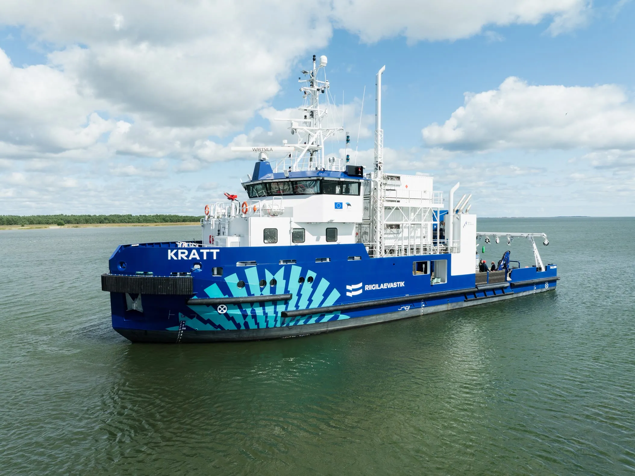
CNG gas fuel systems for vessels
Deck-mounted gas storage, multi-stage pressure reduction, and the automation and documentation that carries the system through classification — engineered for methane-fuelled ships working in Baltic conditions.
Bunkering by container, not by hose
A vessel that burns methane needs gas on board, at engine pressure, in every sea state and at every ambient temperature it will meet. We build that chain end to end: MEGC containers filled at a shore CNG station and lifted onto the deck with the ship’s own crane, a pressure reduction station that takes 250 bar down to burner pressure, and the ventilation, detection, and shutdown logic that keeps the arrangement inside the rules. Refuelling is a container swap at the quay — no bunkering vessel, no permanent fuel tank in the hull.
The equipment behind it comes from the same family we build for road and stationary use — see products and solutions — engineered here for a deck that moves, for salt air, and for a classification society that will read every line of the documentation.
Our current marine system is on a multipurpose work vessel built by Baltic Workboats for the Estonian State Fleet (Riigilaevastik), classed by Lloyd’s Register.
Deck gas storage
MEGC containers with composite cylinders at 250 bar, stacked in deck recesses and secured with twist locks plus cable tensioners. Thermal relief and container ventilation are connected to the vent stack at installation, so the stack is live the moment the container is on board.
Pressure reduction station
Four reduction stages in duty and standby trains with automatic changeover, each stage carrying its own regulator, slam-shut valve, and pressure relief. Nitrogen purge points between stages, fail-close valves throughout, and shock-free equalisation on start-up.
Glycol pre-heating
Heat taken from an engine-room heat exchanger, carried to the deck in a DN50 loop and distributed by actuated valves to an exchanger ahead of every reduction stage. A variable-speed circulation pump holds the flow the exchangers need.
Ventilation and gas detection
Forced ventilation to a deck vent stack, fire flaps on every inlet and outlet, and methane detectors on low, high, and high-high thresholds in each duct. Alarms are raised locally and in the ship’s monitoring system, with separate ventilation modes alongside and at sea.
Automation and integration
Instrumentation into the vessel’s IAMCS over Modbus, a local HMI with full manual backup control, and emergency shutdown logic that isolates by zone rather than dropping the whole gas system on a single signal.
Documentation pack
P&IDs, process description, HAZID report, cause-and-effect matrix, alarm list with limits, software production and quality plan, FAT procedure, operating and maintenance manual, and the connection and pre-lifting checklists the crew works from.
Four stages, because the gas gets cold
Every bar of pressure dropped cools methane by roughly half a degree — the Joule-Thomson effect. Taking 250 bar to engine supply pressure in one step would put the gas far below what any regulator, seal, or steel on deck tolerates, and it would ice the station shut. So the reduction is split into four stages, and each stage gets its heat back before the gas reaches the next one.
How the drop is split between the stages is a design decision, not a standard product. Balancing it keeps every heat exchanger short enough for the space available on deck while the total heating power stays the same.
Design pressure
250 bar
Test pressure
375 bar
Design temperature
−40 to +65 °C
Pipework
AISI 316
Heat exchangers sized for the deck you have
Each stage is pre-heated by a tube-in-tube exchanger in AISI 316 — a 25 × 2.5 mm inner tube inside a DN50 shell — fed from the glycol loop. Internal turbulators lift the overall heat transfer coefficient from 300 to 450 W/m²·K, which brings the longest exchanger down from over 17 m to under 9 m and lets it fit the space the vessel actually has. Heating pipework runs in DN20 at about 1.1 m/s inside 50 mm of mineral wool: on an exposed deck at −30 °C, that insulation is what stands between an 80 °C glycol line and a frozen station.
Safety designed for the worst day
The gas system is built so that every failure has somewhere safe to go. Thermal relief devices open at 110 °C and the station’s pressure relief valves discharge to the same deck vent stack, clear of accommodation and air intakes. Emergency shutdown isolates a section rather than the ship, control valves fail closed, and check valves keep flow one-directional between the containers, the station, and the consumers.
Container walls are A0 rated, door seals intumescent, and every gas-carrying space is ventilated and monitored. Before maintenance the line is isolated, depressurised, and purged with nitrogen — and pressurised with nitrogen again before gas is reintroduced, so the system never passes through a flammable mixture on its way out of service or back into it.
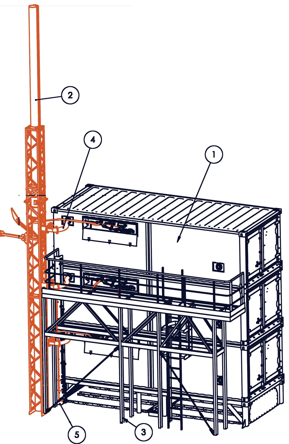
- 1Gas storage containers — three, stacked
- 2Ventilation chimney — the deck vent stack
- 3Service platform and access ladder
- 4Container vent connection, one per container
- 5Gas inlet tower — the bunkering connection
Reference: Baltic Workboats multipurpose work vessel
The CNG supply system on a multipurpose work vessel built by Baltic Workboats for the Estonian State Fleet (Riigilaevastik) is ours, end to end. It feeds methane to four main engines and a gas-fired boiler. Three mobile storage containers sit in a deck recess, each holding 32 cylinders of 282 litres at 250 bar; they are swapped at the quay with the ship’s crane, so the vessel refuels in the time it takes to lift a container. The pressure reduction station runs duty and standby trains with automatic changeover, and the whole system reports into the vessel’s monitoring and alarm system.
The scope ran from the first P&ID through the HAZID workshop, the cause-and-effect matrix, the alarm list, the control software plan, and factory acceptance testing, to the manuals and checklists the crew uses on board — with the gas system reviewed by Lloyd’s Register throughout.
| Item | Specification |
|---|---|
| Gas storage | 3 × mobile storage containers, 32 × 282 L composite cylinders each |
| Working pressure | 250 bar at +15 °C, test pressure 375 bar |
| Consumers | 4 × gas engines and 1 × gas-fired boiler |
| Pressure reduction | 4 stages, duty and standby trains with automatic changeover |
| Pre-heating | Glycol loop from an engine-room heat exchanger, 22 kW total |
| Gas detection | Methane detectors at low / high / high-high in every ventilation duct |
| Relief and venting | Thermal relief at 110 °C and PRVs routed to a deck vent stack with fire flaps |
| Control | Local HMI with manual backup, integrated to the vessel IAMCS over Modbus |
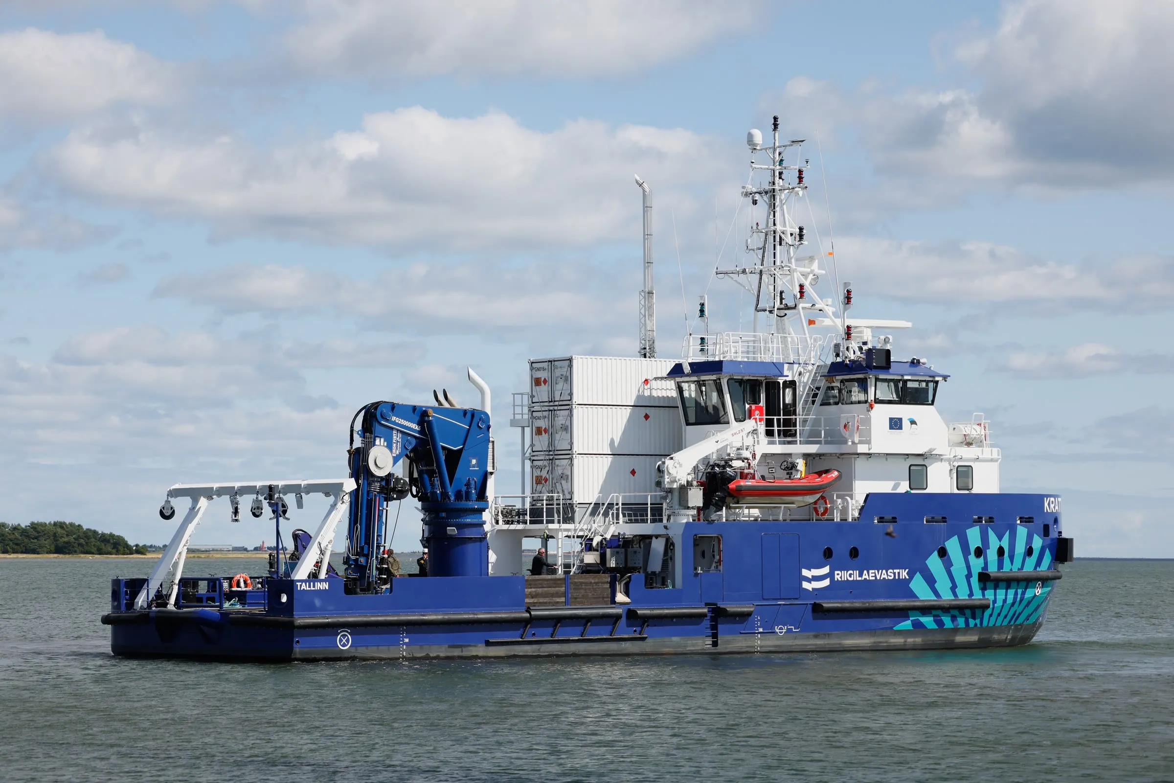
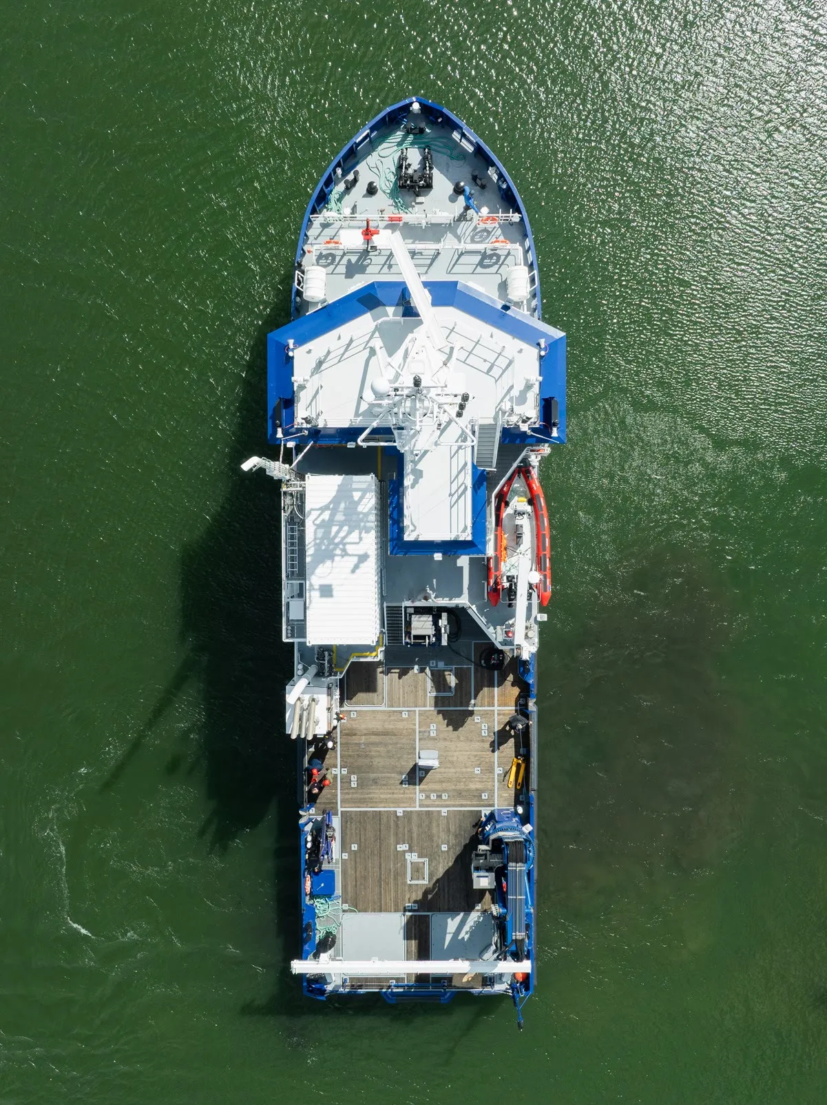
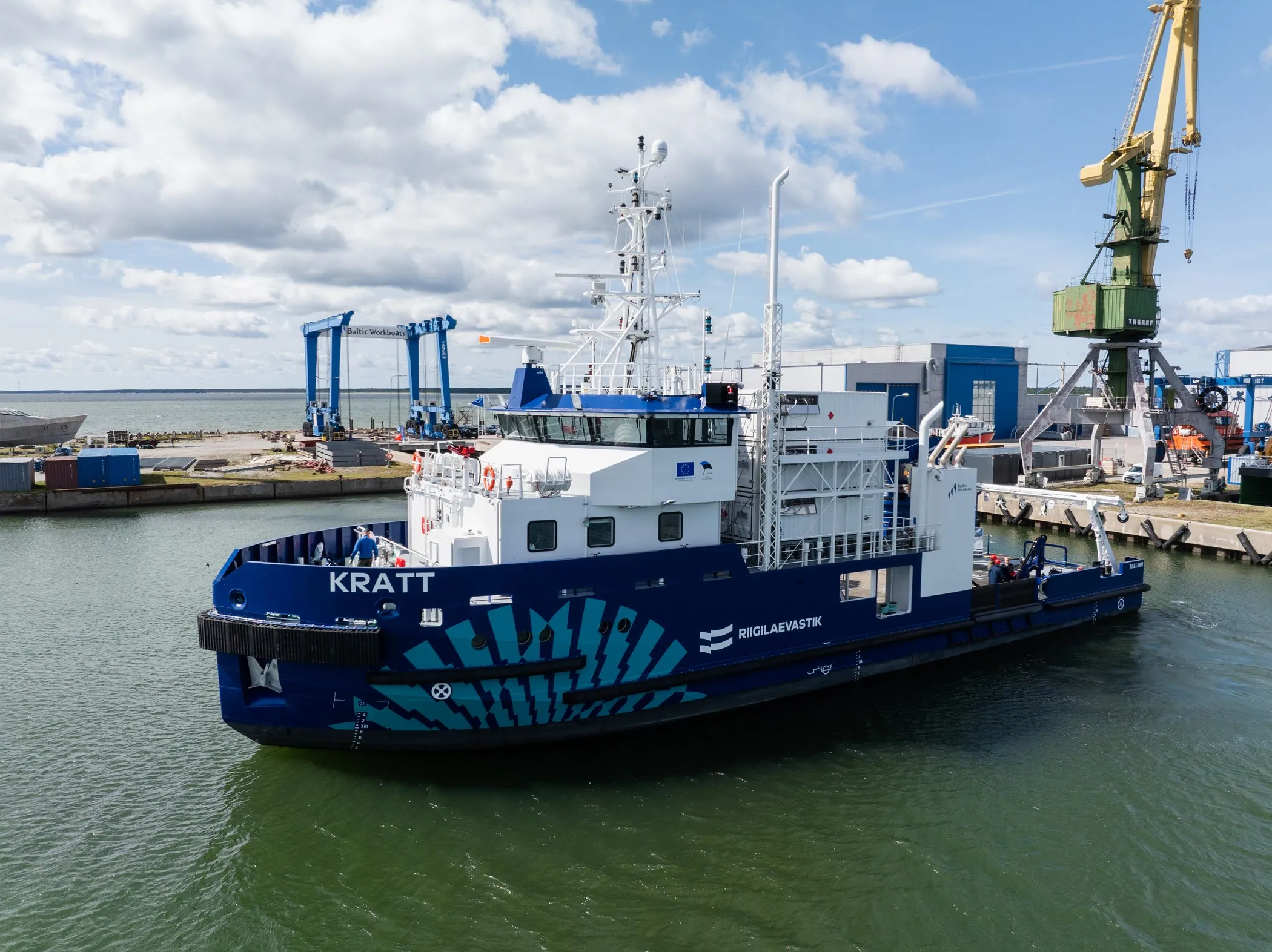
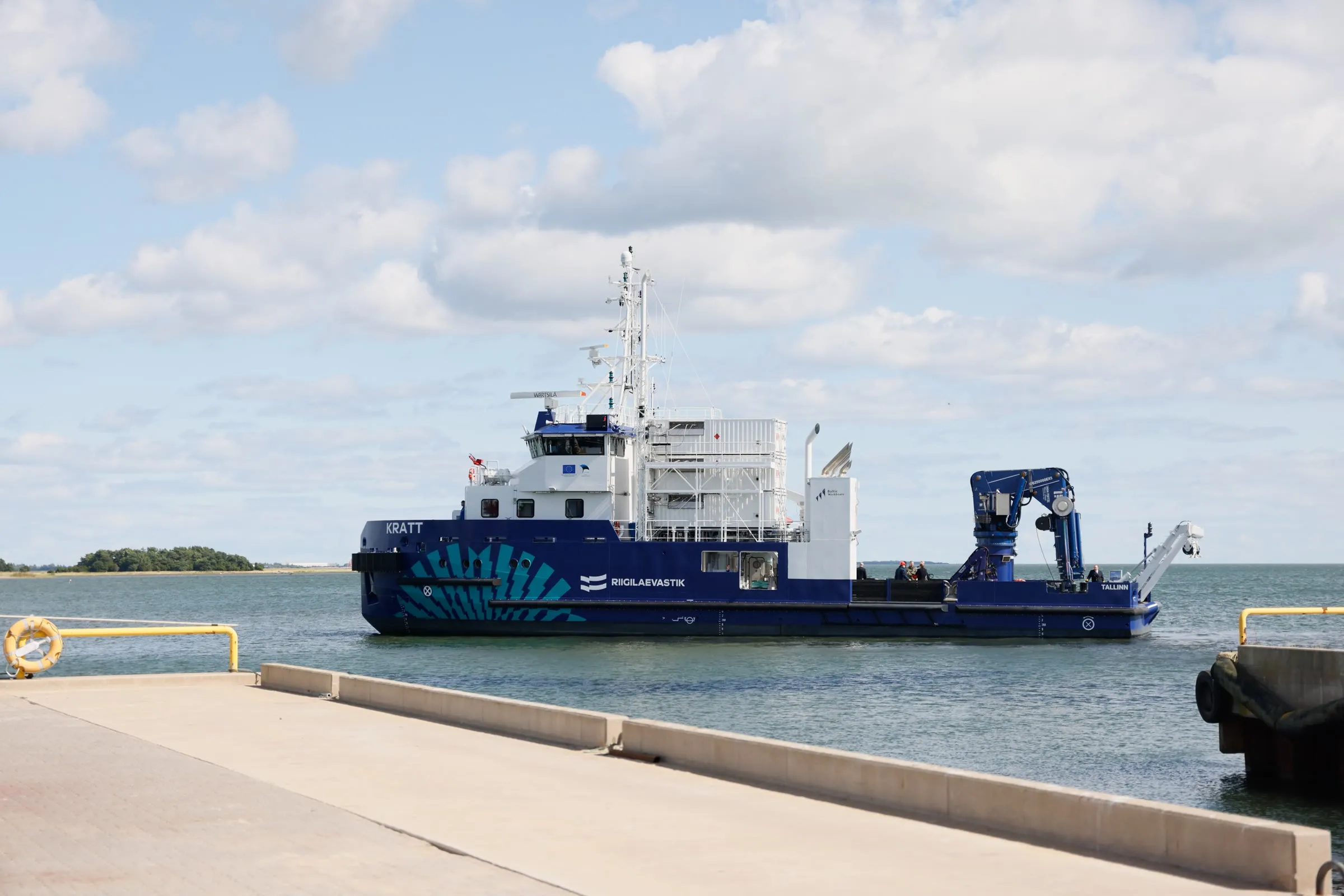
Photography: Robert Markus Liiv.
Built to be approved
The containers are approved under ADR, TPED, and PED. The gas system on board is designed to Lloyd’s Register’s Rules and Regulations for the Classification of Ships using Gases or other Low-flashpoint Fuels, with hazardous-area classification and EX-rated equipment in every gas-carrying space. We prepare the technical file, sit in the HAZID workshop, and answer the class comments until the system is accepted.
- Working pressure on deck
- 250 bar
- Reduction stages, duty and standby
- 4
- Reply to your specification
- 1 day
Planning a gas conversion or a new gas-fuelled build?
Send us the engine data, the deck space, and the operating area — we reply within one working day.